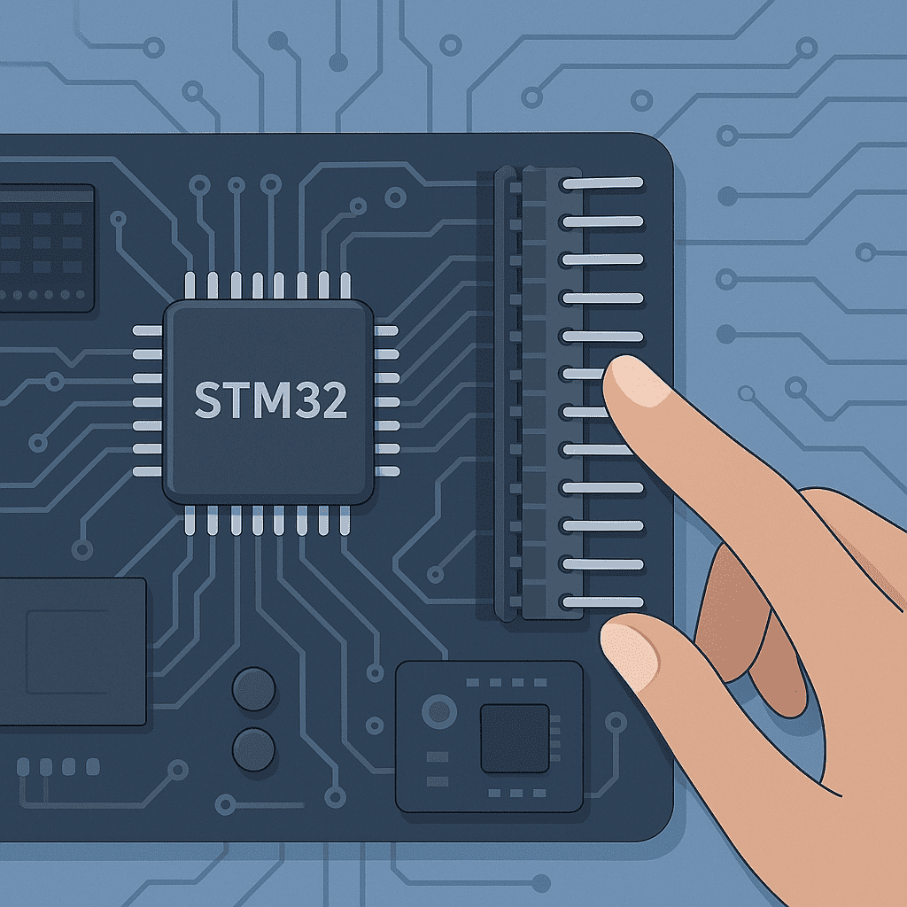
How to Use GPIO Pins in STM32 A Beginner Friendly Tutorial

How to Use GPIO Pins in STM32 A Beginner Friendly Tutorial , If you’re working with STM32 microcontrollers, you’ve likely come across the term GPIO—General Purpose Input/Output. While it might sound basic, GPIO is the foundation for any interaction between your microcontroller and the outside world. From toggling LEDs to reading sensors, mastering GPIO configuration is an absolute must.
However, unlike simpler microcontrollers like AVR or Arduino-based platforms, STM32 GPIOs come with a rich set of configuration options. This richness offers flexibility, but also adds a layer of complexity. In this guide, we’ll explore the key registers—MODER, OTYPER, OSPEEDR, PUPDR, IDR, and ODR—and how to properly configure them for real-world input/output scenarios.
1. Understanding the GPIO Architecture in STM32
STM32 GPIOs are grouped into ports (GPIOA, GPIOB, …, GPIOK depending on the chip). Each port can control up to 16 pins, each of which can be configured independently. Here’s a breakdown of the main registers involved:
| Register | Function |
|---|---|
| MODER | Selects input/output/alternate/analog mode |
| OTYPER | Defines output type (push-pull or open-drain) |
| OSPEEDR | Sets output speed |
| PUPDR | Configures pull-up/pull-down resistors |
| IDR | Reads input pin status |
| ODR | Writes output value |
2. Configuring GPIO as Output
Step-by-Step Example: Turning on an LED
Let’s say we want to turn on an LED connected to PA5:
- Enable GPIOA Clock
RCC->AHB1ENR |= RCC_AHB1ENR_GPIOAEN;- Set Mode to Output (MODER)
GPIOA->MODER &= ~(0b11 << (5 * 2)); // Clear bits
GPIOA->MODER |= (0b01 << (5 * 2)); // Set to output mode- Choose Push-Pull Output (OTYPER)
GPIOA->OTYPER &= ~(1 << 5); // Push-pull- Set Speed (OSPEEDR)
GPIOA->OSPEEDR |= (0b10 << (5 * 2)); // High speed- Disable Pull-up/down (PUPDR)
GPIOA->PUPDR &= ~(0b11 << (5 * 2)); // No pull-up/pull-down- Write to Pin (ODR)
GPIOA->ODR |= (1 << 5); // Turn LED on3. Configuring GPIO as Input
Example: Reading a Button Press from PB3
- Enable GPIOB Clock
RCC->AHB1ENR |= RCC_AHB1ENR_GPIOBEN;- Set Mode to Input
GPIOB->MODER &= ~(0b11 << (3 * 2)); // Input mode- Configure Pull-Up (PUPDR)
GPIOB->PUPDR |= (0b01 << (3 * 2)); // Enable pull-up- Read Input (IDR)
if (!(GPIOB->IDR & (1 << 3))) {
    // Button is pressed (assuming active low)
}
4. Open-Drain vs Push-Pull: What’s the Difference?
- Push-Pull: Actively drives pin HIGH and LOW. Suitable for direct LED or digital output.
- Open-Drain: Can only drive LOW. HIGH is achieved by external pull-up. Useful for I2C communication or multiple devices sharing a line.
Use OTYPER to configure:
GPIOx->OTYPER |= (1 << pin); // Open-drain5. Output Speed Configuration (OSPEEDR)
Output speed affects the slew rate of the pin. This matters for high-frequency signaling.
| Speed Setting | Value | Use Case Example |
|---|---|---|
| Low | 00 | GPIO toggling LEDs |
| Medium | 01 | Low-speed communication |
| High | 10 | SPI, I2C fast mode |
| Very High | 11 | Fast data transfer |
6. Pull-Up and Pull-Down Resistors (PUPDR)
Floating inputs can lead to unpredictable behavior. Use internal pull-ups or pull-downs:
// Pull-up
GPIOx->PUPDR |= (0b01 << (pin * 2));

// Pull-down
GPIOx->PUPDR |= (0b10 << (pin * 2));
FAQ: Common Questions About STM32 GPIO
Q1: Why is my input always reading high or low?
A: Check if the pin is floating. You likely need a pull-up or pull-down resistor.
Q2: Can I use the same pin for input and output?
A: Not at the same time. But you can reconfigure the pin dynamically if needed.
Q3: What happens if I leave OTYPER and OSPEEDR unconfigured?
A: The pin might still work, but not optimally. You risk unintended behavior especially in high-speed or shared-bus setups.
Q4: Is using ODR the only way to write to output pins?
A: You can also use BSRR register for atomic operations:
GPIOx->BSRR = (1 << pin); // Set
GPIOx->BSRR = (1 << (pin + 16)); // Reset
Conclusion: Mastering GPIO—The Key to STM32 Hardware Control
Configuring GPIOs correctly is more than just setting a mode. It’s about understanding how each register shapes the electrical and logical behavior of a pin. With STM32, this granularity gives you power and precision. Whether you’re building a sensor interface, driving a display, or designing a communication protocol, getting your GPIOs right lays the foundation for success.
If you found this article, How to Use GPIO Pins in STM32 A Beginner-Friendly Tutorial, helpful, share it with your friends and visit our website for more tutorials.