
Digital Output Controlling LEDs and Relays with Arduino
Digital Output Controlling LEDs and Relays with Arduino , In the world of electronics and DIY automation, controlling physical components like LEDs and relays through digital outputs is a foundational skill. Whether you’re just starting out with Arduino or building a more advanced home automation system, understanding how to work with digitalWrite(), relays, and safe circuit practices is critical.
This guide covers everything from lighting up an LED to controlling high-voltage devices through a relay. We’ll explore not only the technical details but also practical tips and protective measures often overlooked by beginners.
Introduction to Digital Output with Arduino
Digital outputs are used in microcontroller programming to send a HIGH (5V or 3.3V) or LOW (0V) signal to a connected component. In Arduino, this is achieved using the digitalWrite() function. From blinking an LED to activating a motor or relay, this function acts as the bridge between your code and real-world devices.
Keywords: Arduino digital output, LED control, relay switching, digitalWrite, protect relay circuit
How to Turn an LED On and Off Using digitalWrite()
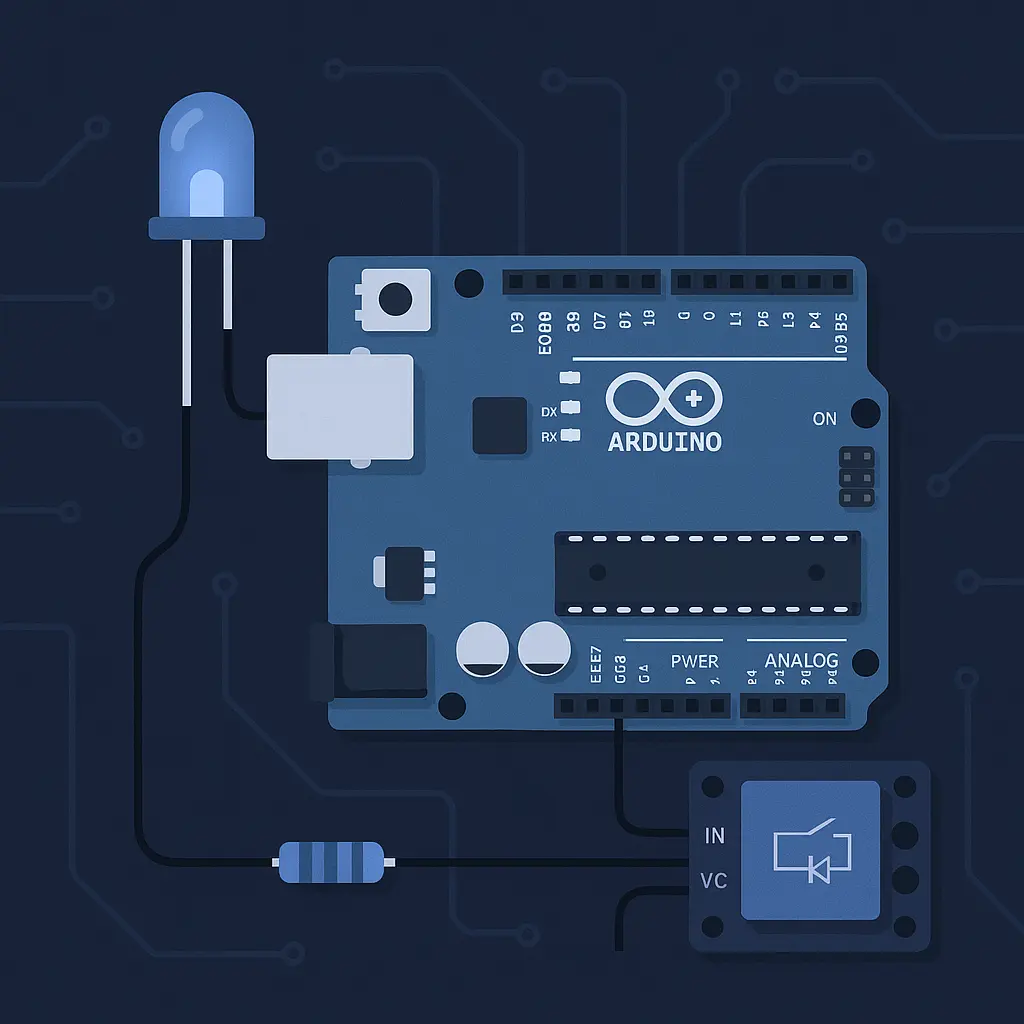
Controlling an LED is often the first step when learning to use digital outputs. Here’s a simple circuit and code example.
Hardware Required:
- 1x Arduino board (e.g., Uno)
- 1x LED
- 1x 220-ohm resistor
- Breadboard and jumper wires
Wiring:
- Connect the LED’s longer leg (anode) to pin 8 via a 220-ohm resistor.
- Connect the shorter leg (cathode) to GND.
Arduino Code:
void setup() {
  pinMode(8, OUTPUT);
}

void loop() {
  digitalWrite(8, HIGH); // Turn LED on
  delay(1000);           // Wait 1 second
  digitalWrite(8, LOW);  // Turn LED off
  delay(1000);           // Wait 1 second
}
This simple loop will blink the LED on and off every second. While it’s straightforward, it’s also foundational for understanding how digital pins behave.
Controlling a Relay with Arduino: Switch AC Devices Safely
Relays are electromagnetic switches that let low-voltage devices (like microcontrollers) control high-voltage appliances. Want to turn on a lamp, fan, or even a water pump using Arduino? You need a relay.
What You Need:
- 1x Relay module (5V relay with opto-isolator recommended)
- 1x Flyback diode (if you’re using a raw relay, more on this below)
- External power supply (recommended for isolation)
- Arduino board
Relay Basics:
- NO (Normally Open): The device is off until the relay is energized.
- NC (Normally Closed): The device is on until the relay is energized.
- COM (Common): The shared terminal.
Wiring Relay Module to Arduino:
- IN to Arduino digital pin (e.g., pin 7)
- VCC to Arduino 5V (or external 5V)
- GND to Arduino GND
Code Example:
void setup() {
  pinMode(7, OUTPUT);
}

void loop() {
  digitalWrite(7, HIGH); // Relay ON (device ON)
  delay(5000);           // Keep device ON for 5 seconds
  digitalWrite(7, LOW);  // Relay OFF (device OFF)
  delay(5000);
}
Crucial Relay Safety: Diode Protection & Power Isolation
When you’re dealing with relays, there are a few important best practices that help protect your components and yourself.
1. Use a Flyback Diode (e.g., 1N4007)
When the coil inside the relay is turned off, it can generate a voltage spike (called back EMF) that can damage your Arduino or transistor. A flyback diode is placed across the relay coil to safely dissipate this energy.
Wiring: Connect the diode in reverse-bias (anode to GND, cathode to VCC of the coil).
2. Use a Relay Module with Opto-Isolator
Opto-isolated relay modules electrically separate the Arduino from the high-voltage section, greatly reducing the risk of damage or noise interference.
3. Separate Power Supplies
For projects that switch AC appliances, it’s best practice to power the relay module from an external power supply instead of Arduino’s 5V pin. This avoids voltage dips or resets.
Practical Use Case: Turning On a Lamp with a Relay
Let’s say you want your Arduino to turn on a desk lamp at sunset.
- Connect the relay to a digital output pin.
- Use a light sensor or real-time clock to determine time of day.
- When it’s dark, trigger the relay to turn on the lamp.
Note: Ensure the AC connection is made safely using an enclosure and insulated wires.
Common Mistakes and How to Avoid Them
- Skipping the diode: Can lead to damaged transistors or microcontrollers.
- Not using opto-isolation: Can cause erratic behavior due to interference.
- Driving the relay directly from the Arduino: The pin may not supply enough current.
- Loose AC wiring: Always secure and insulate your mains connections.
FAQs: Digital Output and Relay Control
Q: Can I control more than one relay with Arduino?
Yes. You can control multiple relays using different digital pins. Use a relay module with multiple channels.
Q: What’s the maximum current Arduino can supply to a relay?
A typical Arduino pin provides about 40mA max. Most relays need more than this, so always use a transistor or module.
Q: Is it safe to connect a 220V device to a relay?
Yes, if done correctly. Always use an enclosure and follow safety standards.
Q: My relay clicks but the device doesn’t turn on. Why?
Check wiring, ensure the correct terminals (NO/COM), and confirm voltage compatibility.
Final Thoughts and Resources
Controlling LEDs and relays might seem like small steps, but they open the door to building powerful and real-world automation systems. Whether you’re automating lights, building an IoT device, or just experimenting, understanding safe digital output practices is crucial.
Always double-check your circuits, respect electrical safety, and don’t skip protective components like diodes and opto-isolators. Remember, a well-built circuit is not just functional, it’s reliable.
If you found this article, Digital Output Controlling LEDs and Relays with Arduino, helpful, share it with your friends and visit our website for more tutorials.